The Basics: Understanding Single-Pole Switch Wiring
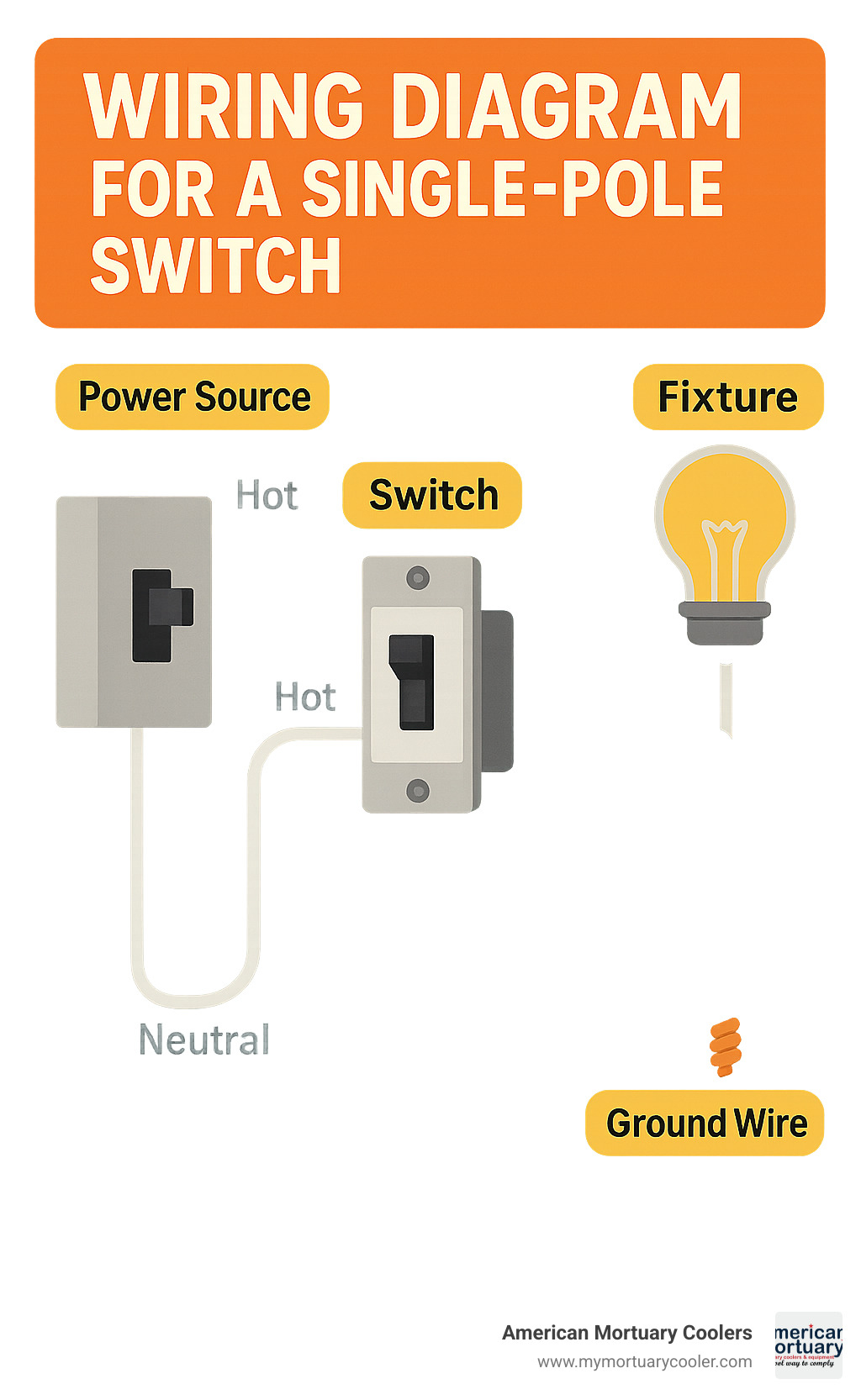
A wiring diagram for a single pole switch is the most common electrical diagram you'll need for basic home lighting control. If you've landed here looking for a quick answer, here's what you need to know:
Basic Single-Pole Switch Wiring:
- Turn off power at the breaker box
- Identify wires: black (hot), white (neutral), bare/green (ground)
- Connect black wires to the two brass terminals (order doesn't matter)
- Connect ground wire to the green screw
- White neutral wires typically bypass the switch (connected together with a wire nut)
Single-pole switches control one fixture from one location with a simple on/off mechanism. This is considered a beginner-level DIY project that typically takes 15-30 minutes and costs between $2-$8 for materials.
The project is straightforward but requires careful attention to safety procedures and proper wire identification. Always verify power is off with a non-contact voltage tester before touching any wires.
I'm Mortuary Cooler, a national-level mortuary cooler supplier with experience in facility electrical systems, including creating and troubleshooting wiring diagrams for single pole switches in cooler installations across funeral homes nationwide.
Similar topics to wiring diagram for a single pole switch:
What Is a Single-Pole Switch and Why It Matters
Ever walked into a room and flipped a switch without giving it a second thought? That's the beauty of a single-pole switch – simple, reliable, and working quietly behind the scenes in nearly every room of your home.
A single-pole switch is the most common light switch you'll encounter – the straightforward on/off switch that controls lighting from just one location. Think of it as a simple gate for electricity: in the UP position, current flows and your light shines; flip it DOWN, and you've closed the gate, stopping electricity from reaching your fixture.
"Single-pole light switch wiring is so straightforward that even homeowners with limited do-it-yourself experience will find it manageable," shared an electrician who recently helped with one of our mortuary cooler installations in Chicago.
What makes a single-pole switch recognizable? Look for these key features:
- Two brass terminal screws where your hot wires connect
- A green grounding screw for your bare copper or green ground wire
- Clear ON/OFF labeling on the toggle or rocker
- A standard rating of 15 amps at 120 volts in most residential settings
The National Electrical Code (NEC) isn't just being fussy when it requires all switches to be properly grounded and housed in appropriate electrical boxes. This is serious safety business. At American Mortuary Coolers, we've seen how proper electrical installation prevents issues in sensitive environments like funeral homes where reliable power is absolutely critical.
| Switch Type | Control Points | Terminals | Common Uses | Wire Requirements |
|---|---|---|---|---|
| Single-Pole | One location | 2 brass + 1 ground | Most room lights, fans | 2-wire + ground |
| Three-Way | Two locations | 3 brass (1 common, 2 travelers) + 1 ground | Hallways, staircases | 3-wire + ground |
| Four-Way | Three+ locations | 4 brass (2 in, 2 out) + 1 ground | Large rooms with multiple entrances | 3-wire + ground between switches |
Single-Pole vs Three-Way vs Four-Way Differences
The main difference between these switch types comes down to one simple question: from how many places do you need to control that light?
With a single-pole switch, there's no confusion – one switch, one location. When it's up, the light's on; when it's down, darkness falls. The position of the switch tells the whole story.
Three-way switches bring more flexibility by letting you control a light from two different spots – perfect for staircases or long hallways. These switches don't have "ON/OFF" markings because either switch can change the light's state regardless of position. They feature three terminals: one "common" terminal (usually darker colored) and two "traveler" terminals that communicate between switches.
"When replacing a three-way switch, always identify the common terminal before disconnecting any wires," warns our lead technician who oversees cooler installations throughout the Northeast. "It's the number one mistake we find when clients attempt DIY electrical work."
Four-way switches take things further, working with two three-way switches to control lighting from three or more locations. With four terminals—two "in" and two "out"—connected to traveler wires, they're less common in homes but essential in larger spaces. We often install these in funeral homes with multiple entrances to ensure staff can easily control lighting from any doorway.
Understanding these differences helps you make informed decisions about which switch type best suits your needs – whether for a simple closet light or a complex hallway lighting system.
Tools, Materials, and Wire Identification
Ready to wire your single-pole switch? Let's gather everything you'll need before diving in. Having the right tools on hand makes this job so much simpler – I learned this the hard way during my first installation at a funeral home in Memphis!
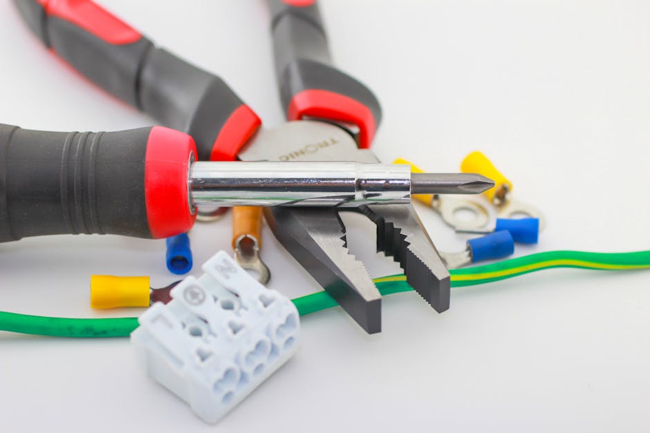
Tools:
- Non-contact voltage tester (your best friend for staying safe)
- Phillips and flathead screwdrivers
- Wire strippers sized for 14-12 AWG wire
- Needle-nose pliers
- Multimeter (great for troubleshooting those head-scratching moments)
- Electrician's tape in various colors (black, white, red)
For materials, you'll need a quality single-pole switch (15A works for most home applications), some wire connectors (those little wire nuts), an electrical box if you're starting from scratch, electrical tape, and possibly a grounding pigtail.
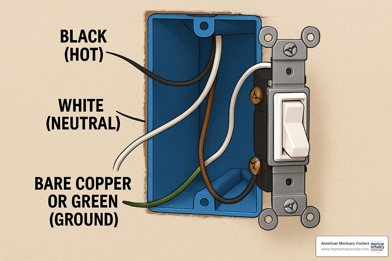
Knowing your wires is absolutely crucial for a safe installation. Think of it as the electrical equivalent of "measure twice, cut once." In standard residential wiring, black wires carry the current (they're hot), white wires provide the return path (they're neutral), and green or bare copper wires are your safety net (they're ground). You might also spot red wires in some setups – these are typically secondary hot wires or travelers in multi-switch configurations.
"I can't tell you how many times proper wire identification has saved us from potential disasters," shares our Atlanta technician. "Especially in funeral homes where sensitive cooling equipment can't afford electrical hiccups."
Most home lighting circuits use either 14 AWG wire (for 15-amp circuits) or 12 AWG wire (for 20-amp circuits). Using the wrong gauge isn't just a code violation – it's a fire hazard waiting to happen.
How to Safely De-Energize and Verify Zero Voltage
Electricity doesn't give second chances, which is why I'm almost obsessive about safety when training our installation teams. Here's my foolproof method for ensuring you're working on a dead circuit:
First, track down the correct circuit breaker. If your panel isn't labeled (and let's be honest, many aren't), ask a helper to watch the light while you flip breakers. Once found, turn that breaker firmly to the OFF position. Some breakers need to be pushed fully off before they reset – don't be shy with it.
In commercial settings like our mortuary facilities, we always use lockout/tagout devices. These prevent someone from accidentally restoring power while you're elbow-deep in wires. Even at home, a simple note taped to the panel can prevent a well-meaning family member from flipping that breaker.
Now comes the verification – my non-negotiable step. Hold your non-contact voltage tester near each wire in the box. Silence and no flashing lights mean you're good to proceed. For absolute peace of mind, I always double-check with a multimeter set to AC voltage (usually 200V setting). Touch one lead to the ground wire and the other to each terminal on the switch – you should see a big fat zero.
"I've been doing this for 15 years," our Southwest technician often says, "and I still test every single time. Electricity doesn't care about your experience level."
Just because the light doesn't turn on doesn't guarantee the circuit is dead. Those few seconds of testing can literally save your life. At American Mortuary Coolers, we've wired countless facilities across 48 states, and we've never had an electrical accident – because we never, ever skip this step.
Step-By-Step wiring diagram for a single pole switch
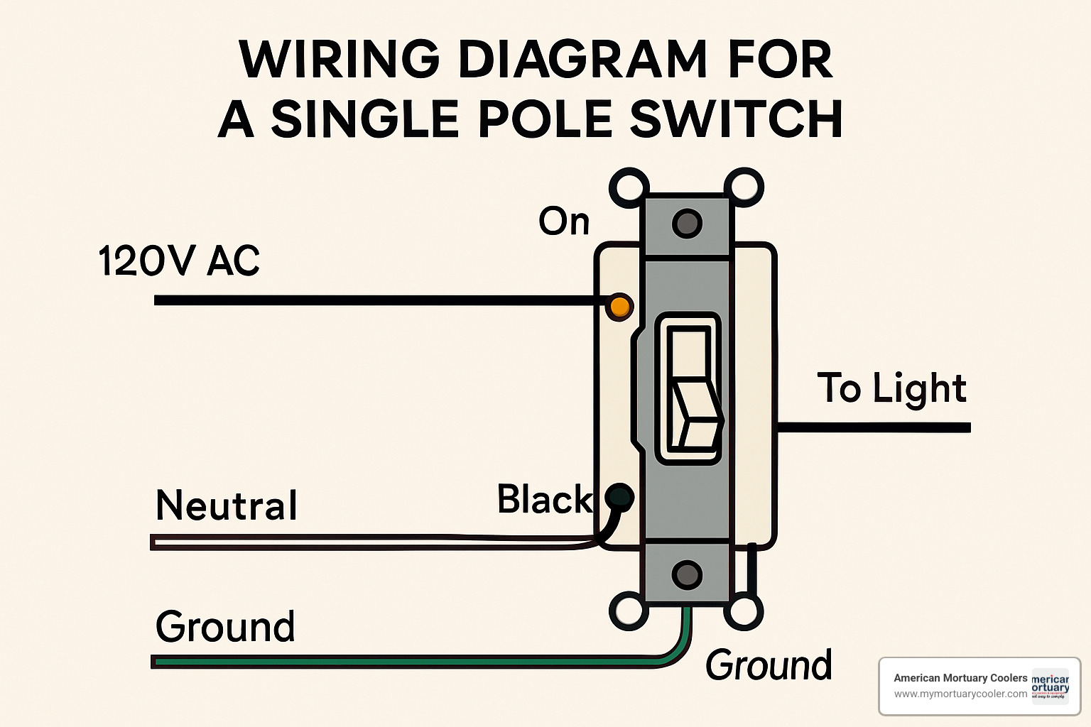
Now that you've gathered your tools and safely de-energized the circuit, let's walk through the installation process with a clear wiring diagram for a single pole switch:

Installing a single-pole switch might seem intimidating at first, but I promise it's quite manageable. I've guided countless funeral home directors through this process during our cooler installations, and they're always surprised by how straightforward it actually is.
First, remove the existing switch if you're doing a replacement. Just unscrew the cover plate, then loosen those mounting screws holding the switch to the box. It should pull out easily, giving you access to the wiring behind.
When you look inside the box, you'll need to identify the wires. You'll typically see black wires (these are your hot conductors), possibly white wires (these are neutral), and green or bare copper wire (that's your ground). The wire identification is crucial—I remember a funeral director in Memphis who mixed these up and, well, let's just say his day got a lot more exciting than planned!
Always connect the ground wire first. It's your safety net. Attach that bare copper or green wire to the green screw on your switch. Think of this as your insurance policy—it needs to be in place before anything else happens.
Next, you'll need to strip the wire insulation if it's not already done. About 5/8" of exposed wire is perfect—not too much, not too little. As my colleague who handles our Midwest installations often says, "It's like a good haircut—just enough to work with, but not so much that things get messy."
Form neat clockwise hooks in your wire ends using needle-nose pliers. This little detail makes a big difference—when you tighten the screw, it actually pulls the wire tighter instead of pushing it away. It's a small trick that professional electricians use that makes connections more secure.
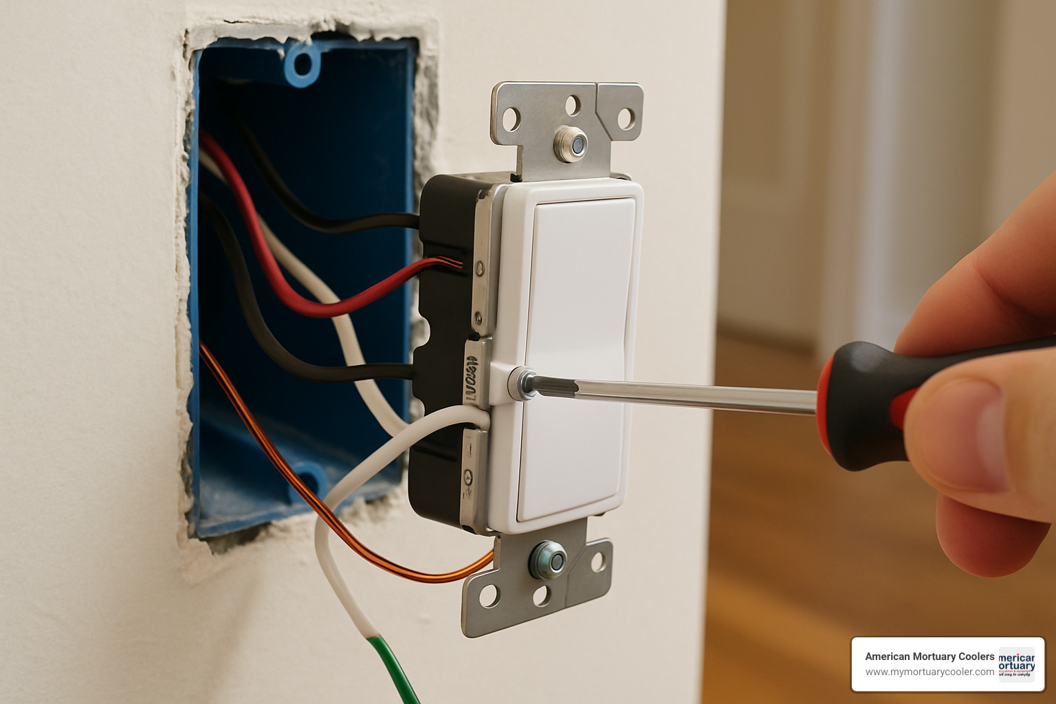
Now it's time to connect the hot wires to those brass terminal screws. One black wire (your power source) goes to one brass terminal, and the other black wire (running to your light fixture) connects to the other brass terminal. The good news? For a single-pole switch, it doesn't matter which black wire goes to which brass terminal—the switch doesn't care about direction.
Tighten those terminal screws to about 12-14 inch-pounds. If you don't have a fancy torque screwdriver (and most homeowners don't), just tighten until firm but not overly tight. Think "snug handshake" not "bone-crushing grip."
After connections are secure, fold and tuck those wires neatly back into the box. This isn't just about being tidy—proper wire arrangement prevents damage and potential shorts. I've seen plenty of switch boxes that look like a bird's nest, and they're usually the ones that cause problems down the road.
Finally, secure the switch to the electrical box with the mounting screws, attach the cover plate, restore power at the breaker, and test your handiwork. That satisfying click as the light comes on is your reward!
wiring diagram for a single pole switch when Power Comes to Switch First
The most common scenario you'll encounter is when the power supply cable enters the switch box first. This setup is found in about 70% of homes and is beautifully straightforward.
In this configuration, the black wire from your power source connects to one brass terminal on the switch. Another black wire runs from the second brass terminal to your light fixture. The white neutral wires from both cables connect together with a wire nut—they bypass the switch entirely since switches only control the hot side of the circuit.
All ground wires should connect to the switch's ground terminal and to the metal box if you have one. At our Pittsburgh facility, we use this configuration for most cooler control systems because it's reliable and simple to troubleshoot.
wiring diagram for a single pole switch when Power Comes to Light First
Sometimes, especially in older homes, you'll find that the power supply enters at the light fixture box first. This creates what electricians call a "switch loop," and it requires a slightly different approach.
In this setup, the black hot wire from your power source connects to a white wire that runs down to your switch. Here's the important part—this white wire is actually being repurposed as a hot wire, so it must be marked with black tape or paint to identify it properly. As my colleague in Columbia, SC likes to say, "Marking that white wire isn't just good practice—it's what separates the professionals from the amateurs."
The black wire in the same cable returns from the switch to the light fixture. At the switch box, you'll connect the marked white wire to one brass terminal and the black return wire to the other brass terminal. Don't forget the ground wire to the green screw!
Back at the fixture box, connect the original black power wire to your marked white switch wire, the black wire from the switch to the black fixture wire, and the original white neutral wire directly to the white fixture wire. All ground wires should be connected together and to the fixture.
I've encountered this setup frequently when installing mortuary coolers in historic funeral homes throughout New England. It looks complicated on paper, but once you understand the flow of electricity, it makes perfect sense.
Want to learn more about mastering electrical projects? Check out our guide on how to succeed at wiring a single light switch even if you've had trouble in the past.
Common Mistakes and How to Avoid Them
After installing electrical systems in hundreds of mortuary coolers nationwide, we've seen just about every mistake possible with wiring diagram for a single pole switch installations. Let me share the most common pitfalls we encounter—and how you can avoid them in your own projects.
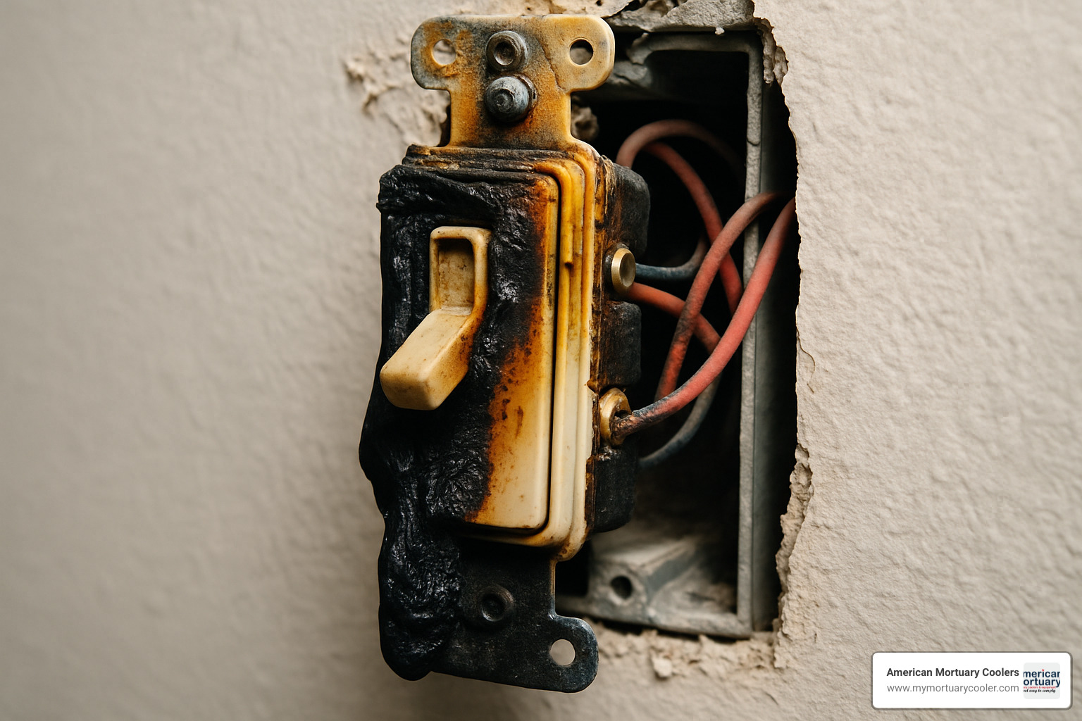
Loose connections are probably the number one issue we spot during our service calls. When terminal screws aren't tightened properly, they create resistance, which generates heat. Over time, this can lead to arcing, melted insulation, and even electrical fires. After connecting each wire, give it a gentle tug to check security, and always tighten those terminal screws to 12-14 inch-pounds—snug, but not overtightened.
"I can't tell you how many times I've arrived at a facility to find a switch that's warm to the touch," our Nashville technician told me recently. "That's a telltale sign of a loose connection that's just waiting to cause problems."
Missing ground connections might not cause immediate problems, but they eliminate your safety net if something goes wrong. Our Rocky Mountain Region technician puts it bluntly: "Never skip the ground wire—it's like driving without a seatbelt." Always connect that bare copper or green wire to the green screw on the switch and to the metal box if you're using one.
Over-stripping wires is a rookie mistake we see quite often. When you remove too much insulation, bare copper can extend beyond the terminal and create shock hazards or short circuits. Stick to the 5/8" guideline—it provides enough copper for a solid connection while keeping everything safely contained within the terminal.
Box overfill is particularly common in older buildings where people have added wiring over time. Cramming too many wires into an electrical box isn't just messy—it violates code and creates fire hazards as wires get damaged or overheat. The National Electrical Code specifies maximum fill calculations based on wire count and size. During a recent installation in Chicago, we had to replace several undersized boxes to meet code requirements before we could even begin installing our cooler controls.
Not testing after installation is a mistake even professionals sometimes make when they're in a hurry. Always restore power and test your work thoroughly. A non-functioning switch might indicate a simple wiring error, while flickering lights could signal something more concerning like a loose connection.
Many DIYers also cut corners on materials. "I once arrived at a funeral home to find masking tape instead of electrical tape on some connections," our Southeast Region specialist shared with a laugh. "They saved maybe fifty cents and created a serious hazard." Always use properly rated electrical materials—this isn't the place to pinch pennies.
Does Terminal Order Matter on a Single-Pole?
We get this question all the time, and I'm happy to provide a clear answer: No, it doesn't matter which hot wire connects to which brass terminal on a standard single-pole switch. The terminals are completely interchangeable.
That said, there are good reasons why I still recommend following a consistent pattern. When you establish a habit—like connecting power in at the top terminal and power out at the bottom—troubleshooting becomes much simpler down the road. If you or another electrician needs to modify the circuit later, a consistent approach reduces confusion and saves time.
"Terminal order doesn't affect function," explains our lead electrician who services our Johnson City headquarters, "but I always connect line to the top terminal and load to the bottom. It's about creating good habits that translate to more complex installations later on."
Professional electricians typically follow these consistent patterns, making their work easily recognizable and serviceable by others. It's like keeping a tidy toolbox—it might not affect how well the tools work, but it sure makes finding what you need a lot easier when you're in a hurry!
At American Mortuary Coolers, we've found that these small attention-to-detail practices have saved us countless hours of troubleshooting during installations across the country. Whether we're in a modern facility in Los Angeles or a historic funeral home in Boston, following consistent wiring practices helps ensure our coolers operate flawlessly for years to come.
Special Scenarios and Upgrades
As you become more comfortable with basic wiring diagrams for single pole switches, you'll likely encounter situations that go beyond the standard setup. Let's explore some common special scenarios you might face in your home electrical projects.
Dimmer Switch Replacement
Swapping your regular switch for a dimmer follows similar wiring principles, but with a few key differences that are important to note:
Most modern dimmers come with wire leads instead of terminal screws, which changes how you make connections. Simply connect the dimmer's black lead to your incoming hot wire, and the red lead to the wire heading to your light fixture. Don't forget to connect that green ground lead to your ground wire – safety first!
"When we install dimmers in funeral homes, we always double-check LED compatibility," our Pacific Region specialist told me recently. "There's nothing worse than installing everything perfectly only to have lights that flicker or buzz because the dimmer and fixtures don't play nicely together."
Before purchasing, verify your light fixtures are dimmer-compatible, especially if you're using LED or fluorescent lighting, as some budget fixtures don't dim well or at all.
Smart Switch Installation
The biggest difference with smart switches is their need for a neutral wire connection. This is what powers the switch's wireless features and display even when the light is off:
Connect your line and load wires just like a standard switch, but you'll also need to connect the white neutral wire to the neutral terminal on your smart switch. The ground wire still goes to the ground terminal, of course.
Many older homes don't have neutral wires in their switch boxes, which can be a roadblock. If you're facing this issue, you have two options: purchase a special no-neutral smart switch (they exist but have limitations), or have an electrician run a proper neutral wire to your switch box.
Controlling Outlets with a Switch
Want to control a lamp or other device with a wall switch? Your single pole switch can easily control outlets too:
For a fully switched outlet, wire it exactly as you would a light fixture. But what if you want one receptacle always on and one controlled by the switch? You'll need to break off the small connecting tab between the hot terminals on the outlet, then wire the always-on receptacle directly to power and run the switched receptacle through your switch.
"In our mortuary installations," explains our Chicago-area technician, "we often set up switched outlets for equipment that benefits from controlled power cycling. It's a simple solution that adds a lot of convenience."
Switch Loop Troubleshooting
If you open a switch box and find only one cable containing a black and white wire with no other neutral wires, you're likely dealing with a switch loop. This means power comes to the light fixture first, then loops down to the switch.
In this case, that white wire isn't actually a neutral – it's being used as a hot wire and should be marked with black tape (if it isn't already, please mark it for safety). Connect both wires to the brass terminals and the ground wire to the green screw.
This setup was common in older homes, and while it's not ideal for modern smart switches (which need neutrals), it works perfectly fine for standard switches.
Grounding and Metal Boxes
Proper grounding isn't just code-required – it could save your life. How you ground depends on your box type:
With plastic boxes, simply connect the ground wire directly to the green ground screw on the switch. Easy!
For metal boxes, you'll need to be more thorough. Connect a pigtail from the ground wire(s) to the metal box using a proper grounding screw. Then connect another pigtail from this connection to the switch's ground terminal. This ensures both your switch and box are safely grounded.
When dealing with multiple ground wires, use a wire connector to join all ground wires plus a pigtail that connects to the switch.
"At our Dallas facility," our Southwest specialist shared, "we're extremely careful with grounding because our mortuary coolers have sensitive electronic controls. Good grounding prevents both safety hazards and protects equipment from electrical noise damage."
Proper grounding isn't where you should cut corners – it's your electrical safety net when something goes wrong.
Testing, Troubleshooting, and When to Call a Pro
After you've finished installing your single-pole switch, taking time to properly test your work isn't just a good idea—it's essential for safety and peace of mind. Let me walk you through this final but crucial step.
Testing Your Installation
Before you flip that breaker back on, take a moment for a careful visual inspection. Make sure all your connections are tight and secure, with no bare copper peeking out where it shouldn't be. It's these little details that make the difference between a professional-quality installation and a potential hazard.
"I always triple-check my connections before restoring power," shares our Nashville technician. "It only takes 30 seconds but can prevent hours of troubleshooting—or worse, a fire hazard."
Once you're confident everything looks good, it's time to restore power at the breaker panel. Then, simply toggle your new switch on and off to verify the light responds correctly. While the light is on, pay attention to any unusual sounds or visual cues—your switch shouldn't buzz, your light shouldn't flicker, and the switch face should remain cool to the touch.
Common Troubleshooting
Even with careful installation, sometimes things don't work as expected. Don't worry—most issues have simple solutions.
If your switch doesn't turn on the light, start with the basics. Is power restored at the breaker? Sometimes breakers don't fully reset unless you flip them completely off before turning them back on. Next, check for loose connections by gently wiggling each wire. It's also worth testing the light fixture with a bulb you know works—I can't tell you how many times I've seen people troubleshoot complex wiring issues only to find they had a burned-out bulb!
When a breaker trips immediately after you turn on your new switch, you're likely dealing with a short circuit. This requires immediate attention. Turn everything off and look for pinched wires or any bare copper touching the metal box. Even a single strand of wire in the wrong place can cause this problem.
"During a recent installation in our New York facility," recalls our technician, "we encountered a tripping breaker caused by a tiny strand of copper touching the box. These small details matter tremendously in electrical work."
If your switch feels warm or makes buzzing noises, turn it off right away. This typically indicates either loose connections that are causing resistance and heat, or that the switch isn't properly rated for the load it's controlling. Either way, it's a fire hazard that needs immediate correction.
When to Call a Professional
While replacing a wiring diagram for a single pole switch is generally DIY-friendly, there are definitely situations where calling in a pro is the wisest choice. Here's when to pick up the phone:
If you find multiple switches controlling one light, you're likely dealing with three-way or four-way switch configurations, which follow different wiring principles than standard single-pole switches.
The presence of aluminum wiring (silver-colored rather than copper) requires special handling and connections—this was common in homes built between 1965 and 1975, and improper connections with aluminum can create fire hazards.
When you find no ground wire in an older installation, a professional can help determine the safest approach to upgrading your system.
Repeated breaker tripping despite your troubleshooting efforts suggests a more complex issue that requires professional diagnosis. Similarly, any signs of previous heat damage or charring inside the box are red flags that warrant expert attention.
"We always emphasize to our clients across all regions that electrical safety isn't about saving a few dollars," states our lead technician. "If you're uncertain at any point, the cost of hiring a professional is insignificant compared to the potential costs of fire damage or injury."
At American Mortuary Coolers, we understand the importance of proper electrical work—our sensitive cooling systems depend on it. Whether you're wiring a simple switch or installing complex equipment, never compromise on electrical safety.
Frequently Asked Questions about Single-Pole Switch Wiring
Which wire is line and which is load?
One of the most common questions we hear from customers across all our service regions relates to identifying line and load wires. Simply put, the line wire brings power from your electrical panel to the switch, while the load wire carries that power from the switch to your light fixture.
In typical installations, you can often tell them apart by their position in the box. The line wire usually enters from the bottom of the box or comes directly from the panel, while the load wire typically exits the top of the box as it heads toward your ceiling fixture.
"If you're scratching your head trying to figure out which is which, here's a simple trick," shares our Columbia SC specialist with a smile. "You can use a voltage tester after briefly turning the power back on. The line wire will show voltage regardless of whether the switch is on or off, while the load wire only shows voltage when the switch is flipped on."
Just remember to turn that power off again before making any connections! Safety first, always.
What if I find a white wire on the switch?
Finding a white wire connected to your existing switch might seem confusing, but don't worry – you've likely encountered what we call a "switch loop" configuration. This happens when:
The power supply enters at the light fixture first (rather than the switch) A white wire has been repurposed as a hot wire to bring power down to the switch This white wire should be marked with black tape or paint to identify it as hot
"The National Electrical Code is pretty clear about this," our Pittsburgh specialist explains while adjusting his safety glasses. "Any white wire used as a hot conductor must be marked with black or red tape. If yours isn't marked, you should definitely add that marking during your installation – it's not just good practice, it's required for safety."
When reconnecting everything, treat this marked white wire exactly as you would a black hot wire. The marking helps prevent confusion for anyone who might work on the switch in the future.
Can a single-pole switch control an outlet?
Absolutely! Using a wiring diagram for a single pole switch to control an outlet is quite common, especially in rooms where floor lamps provide the primary lighting. Many of our customers in older homes use this setup for greater flexibility.
You have two main options when wiring a switched outlet:
For a fully switched outlet where the entire receptacle is controlled by the switch, you'd wire it exactly as you would a light fixture. This means when the switch is off, the outlet has no power at all.
For a half-switched outlet (where one receptacle is always on and the other is controlled by the switch), you'll need to break off the small connecting tab between the hot terminals on the outlet. Then connect the unswitched hot wire directly to one terminal and the switched hot wire to the other. The neutral remains connected to both sides, providing a complete circuit.
"I remember our Atlanta installation where we created switched outlets for UV sanitizing equipment in the mortuary cooler room," our Southeast Region technician shares warmly. "This clever setup allowed the staff to control the sanitization cycle without having to directly access the equipment each time. It's a simple solution that made their daily operations much more efficient."
Whether you're controlling a mortuary sanitization system or just a reading lamp in your living room, a properly installed switched outlet offers wonderful convenience with the same basic wiring principles we've discussed throughout this guide.
Conclusion
Understanding the wiring diagram for a single pole switch is more than just a handy DIY skill—it's an essential piece of knowledge that empowers you to take control of your home or facility's electrical systems. Throughout this guide, we've walked through the fundamentals together, breaking down what might seem complex into manageable, straightforward steps.
At American Mortuary Coolers, we've seen how electrical knowledge helps our clients maintain their facilities with confidence. Our team doesn't just install specialized cooling equipment—we partner with funeral homes across the country to ensure every aspect of their operation runs smoothly, right down to the light switches.
I'd like to leave you with some key takeaways that our technicians emphasize during every installation:
Safety is never optional. Always turn off power at the breaker and double-check with a voltage tester before touching any wires. This simple habit has prevented countless accidents in our decades of service.
Know your wires. Taking the time to properly identify line, load, neutral, and ground connections means the difference between a successful installation and a potentially dangerous situation. As our Chicago technician often says, "The few extra seconds spent identifying wires saves hours of troubleshooting later."
Secure connections create lasting results. Those extra turns on the terminal screws and properly stripped wires might seem minor, but they're what prevent callbacks and hazards down the road. Our Dallas team recently revisited a 10-year-old installation where every connection was still perfect—because they did it right the first time.
Respect the code. Local electrical codes aren't just red tape—they're safety standards developed from real-world incidents. Following them protects your property and, more importantly, the people who use it every day.
Recognize your limits. Even our most experienced technicians know when to call in specialists for certain tasks. There's wisdom, not weakness, in seeking help when a job exceeds your comfort level.
Whether you're replacing a single switch in your hallway or planning electrical work for your entire funeral home, the principles we've shared will serve you well. And remember, if you're in the funeral industry and need reliable, custom mortuary coolers with expert installation, our team at American Mortuary Coolers delivers directly to all 48 contiguous states—bringing not just equipment, but expertise to your doorstep.
For more information about our complete cooling solutions or assistance with any technical questions, we're just a phone call away. After all, what matters most isn't just getting the job done—it's getting it done right, safely, and with confidence.


