DIY Light Switch Wiring Made Simple
If you're looking for a wiring diagram single light switch, here's a quick reference guide:
-
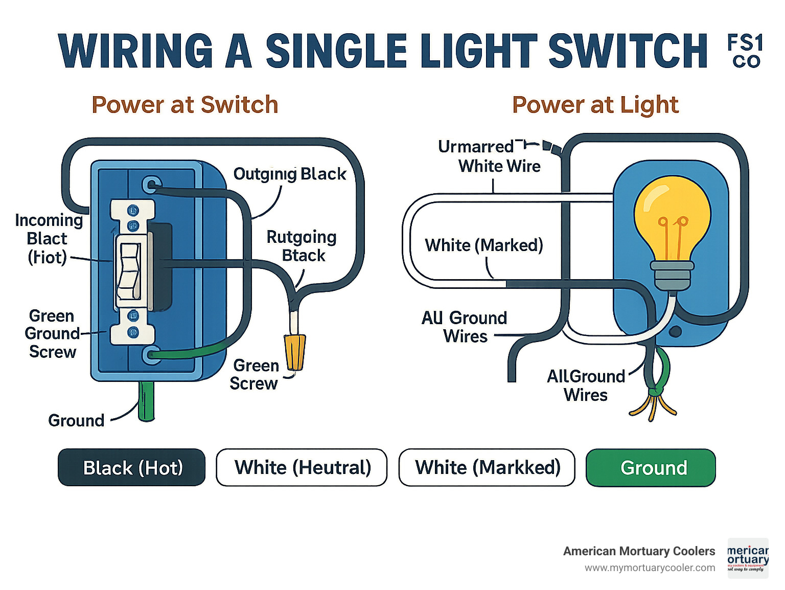
Power at Switch Box Configuration:
- Connect incoming black hot wire to one brass terminal
- Connect outgoing black wire (to light) to the other brass terminal
- Connect ground wire to green ground screw
- Cap white neutral wires together with wire nut
-
Power at Light Fixture Configuration:
- Connect black wire from light to black wire going to switch
- Connect white wire marked with black tape from switch to light's hot terminal
- Connect unmarked white wire to light's neutral terminal
- Connect all ground wires together
Wiring a single light switch is one of the most straightforward electrical projects a homeowner can tackle. Taking just 15-30 minutes and costing between $2-$8 in materials, this beginner-level DIY job can save you the expense of calling an electrician for a simple task.
Single-pole light switches are the most common type found in homes, used in over 80% of lighting circuits. They control one light (or group of lights) from a single location. While the concept is simple—the switch interrupts the flow of electricity like a drawbridge stops traffic—proper installation requires understanding a few basic wiring principles and safety precautions.
Whether you're replacing an old switch, upgrading to a dimmer, or installing a brand new fixture, knowing how to read and implement a wiring diagram is critical to your success and safety.
I'm Mortuary Cooler, a national-level cooler supplier with experience in electrical systems including wiring diagram single light switch installations across numerous facility projects. My background in commercial electrical work has given me practical insights into making complex wiring concepts accessible to beginners.
Essential wiring diagram single light switch terms:
Single-Pole Switch Basics & Safety Prep
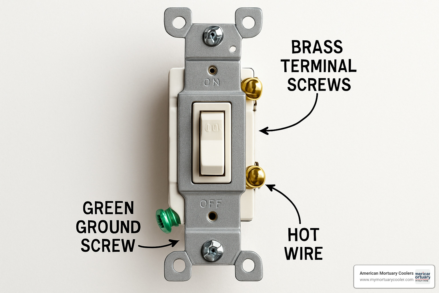
Let's get friendly with the humble single-pole switch before we start connecting wires. This little device is the workhorse of home lighting—the most common switch you'll encounter in any house. Look closely and you'll notice it has two brass terminal screws (these connect to your hot wires) and a green screw for grounding. Nothing fancy, but incredibly effective at controlling a light from one location.
The National Electrical Code (NEC) has some specific requirements about installing these switches properly. Don't worry—I'll walk you through the important bits so you'll stay safe and code-compliant, whether you're working with a metal or plastic electrical box.
How Does a Single-Pole Switch Work?
Think of your light switch like a drawbridge over a river. When the switch is flipped to "on," the drawbridge lowers, creating a path for electricity to flow across to your light fixture. Flip it "off," and the drawbridge raises, stopping the electrical traffic completely.
"A single-pole light switch interrupts the hot conductor in a circuit," a veteran electrician with 30 years of experience once told me. "It's like a drawbridge that stops traffic when raised. Such a simple mechanical action, but it gives you complete control over your lighting."
What's interesting is that the switch only controls the outbound journey (the hot wire)—it doesn't affect the return path (neutral wire). This simple principle is what makes these switches so reliable and long-lasting.
Tools & Materials Checklist
You probably already have most of what you need in your toolbox. For this job, gather up your flathead and Phillips screwdrivers, wire strippers, needle-nose pliers, and a non-contact voltage tester (this one's non-negotiable for safety). You'll also need some wire nuts, electrical tape (black), and of course, your new single-pole switch.
Material-wise, you'll typically work with 2-wire Romex cable, which contains black, white, and bare ground wires. You might also need a grounding pigtail and a switch plate cover to finish things off nicely.
The best part? This is an incredibly affordable DIY project. The switch itself usually costs between $2-$8, depending on whether you go basic or fancy. If you're feeling adventurous, you might consider a dimmer switch instead—just make sure it's compatible with your lighting.
Safety First: Shutting Off and Testing
I can't stress this enough—electricity demands respect. Before you even think about touching those wires, follow these safety steps:
- Find your breaker panel and turn off the circuit that powers your switch.
- If your panel isn't clearly labeled (and let's be honest, many aren't), turn on the light controlled by the switch, then flip breakers until the light goes out.
- Place a lockout tag on the breaker to prevent anyone from accidentally turning it back on while you're working.
- Always test for power with your non-contact voltage tester—even if you're 100% sure the power is off.
A professional electrician I know always says, "Trust but verify when it comes to power. That voltage tester has saved me from nasty shocks more times than I can count." This simple habit has prevented countless injuries among pros and DIYers alike.
Identifying Hot, Neutral & Ground Wires
Wire colors are like a secret code that tells you what each wire does:
Black or red wires typically carry current (they're "hot"). White wires usually provide the return path (they're "neutral"). Bare copper or green wires are your safety net (they're "ground").
But here's a curveball that trips up many DIYers: in some setups, particularly in switch loops, a white wire might actually be used as a hot wire. When you see this, the white wire should be marked with black tape or paint on both ends. This isn't just a helpful tip—it's required by electrical code to prevent dangerous mistakes.
"One of the most common errors I encounter," a master electrician once shared with me, "is people not properly identifying a white wire that's being used as a hot conductor. Always mark these with black tape to avoid potentially dangerous wiring confusion."
Understanding these basics will help ensure your wiring diagram single light switch project goes smoothly and safely. Taking the time to learn these fundamentals isn't just about getting the job done—it's about doing it right and keeping your home and family safe.
Wiring Diagram Single Light Switch Explained
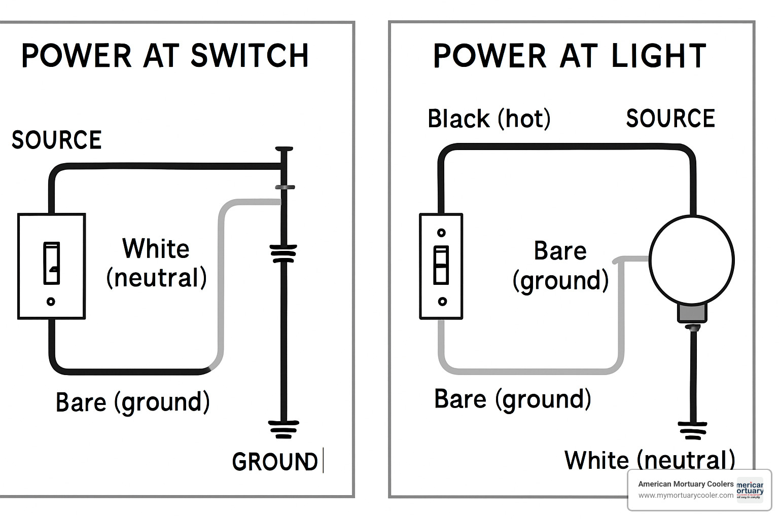
When it comes to wiring a single light switch, you'll encounter one of two main setups in your home. Think of these as different roads leading to the same destination – a working light you can control. Let me walk you through both scenarios in plain English.
The first setup has power arriving at your switch box first (like getting mail delivered directly to your door), while the second has power arriving at the light fixture first (like having your mail go to a neighbor who then brings it over). Both work perfectly well, but knowing which one you're dealing with makes all the difference.
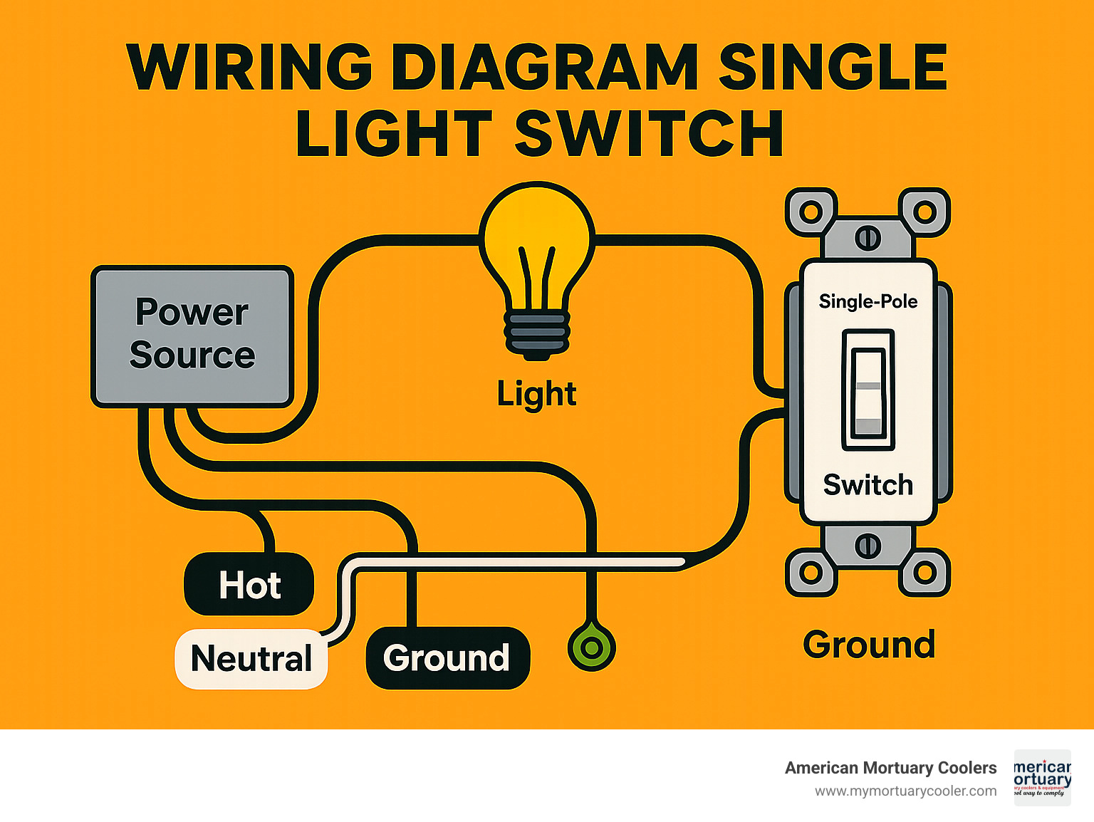
wiring diagram single light switch: Power at the Switch Box
This first setup is the electrical equivalent of a straight shot – simple and direct. When power comes to your switch first, everything flows naturally.
Your black hot wire from the power source connects to one of the brass terminals on your switch. Think of this as electricity knocking at the door. The second brass terminal connects to another black wire that runs up to your light fixture – this is like opening the door and letting electricity through when the switch is flipped on.
The white neutral wires don't connect to the switch at all. Instead, they connect to each other with a wire nut, creating a continuous return path. As my grandfather (who was an electrician for 40 years) used to say, "Electricity always wants to go home" – and that's what the neutral wire allows.
Your ground wires (bare copper or green) connect to the green screw on the switch and to the metal box if you have one. Safety first!
"I love this configuration because it's as straightforward as making a sandwich," says Maria, a residential electrician I spoke with. "The switch simply interrupts the flow of power like your hand stopping midway through making lunch."
wiring diagram single light switch: Power at the Light Fixture
This second setup – called a "switch loop" – is like a detour on your electrical roadmap. The power arrives at the light fixture first, then travels down to the switch and back up again.
In this scenario, the black hot wire from your power source connects to one wire of the cable going to the switch. Here's where it gets interesting: the white wire in that same cable isn't acting as a neutral anymore. Instead, it's repurposed as a hot wire (or "switch leg") that returns power to the light.
Because we're using a white wire in an unusual way, electrical code requires you mark it with black tape or paint on both ends. This is like putting a "this isn't what it seems" warning label on it. This marked white wire connects to the second terminal on your switch.
When power returns from the switch, the black wire connects to your light fixture, completing the circuit when the switch is on. Meanwhile, the unmarked white wire from the power source connects directly to the light fixture as the true neutral.
"The key to a switch loop is respecting the white wire's new identity," explains Tom, who's been wiring homes for 25 years. "It's like when your friend changes careers – you need to update how you think of them!"
Comparing Single-, Three- & Four-Way Switches
While we're focused on single-pole switches today, it's worth understanding how they compare to their more complex cousins:
| Switch Type | Number of Terminals | Control Points | Typical Uses |
|---|---|---|---|
| Single-Pole | 2 brass + 1 ground | One location | Standard room lighting |
| Three-Way | 3 brass + 1 ground | Two locations | Hallways, stairways |
| Four-Way | 4 brass + 1 ground | Three or more | Large rooms with multiple entries |
Your basic single-pole switch has "ON/OFF" markings on the toggle and lets you control a light from just one spot. It's the electrical equivalent of a simple yes/no question.
Three-way switches lack these markings and work in pairs. They're perfect for controlling lights from two locations – like at both ends of a hallway. No more walking through dark spaces to find the switch!
Four-way switches are the social butterflies of the electrical world, installed between two three-way switches to create control from three or more locations. Perfect for large open spaces with multiple entry points.
"I always tell my DIY workshop students to think of switches like team members," says electrical systems instructor Jamie. "Single-pole works alone, three-way works in pairs, and four-way brings everyone together for the win."
Step-by-Step Wiring Guide & Advanced Options
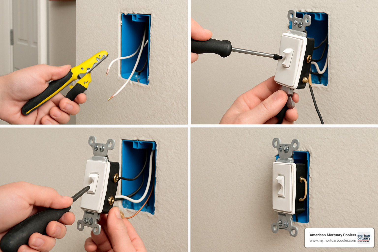
Now that we've covered the theory, let's roll up our sleeves and get practical with installing your light switch. I've broken this down into manageable steps that even first-time DIYers can follow with confidence.
Step 1-6: Standard Installation Walkthrough
First things first - safety comes first. Head to your circuit breaker panel and turn off the appropriate breaker. Don't skip using a voltage tester to double-check the power is truly off before you touch anything. Better safe than sorry!
If you're replacing an existing switch, carefully remove the wall plate by unscrewing it. Then loosen the mounting screws holding the switch to the box. Gently pull the switch out from the wall, but keep those wires connected for now so you can see what goes where.
Take a moment to study the existing setup. I always recommend snapping a quick photo with your phone – this simple trick has saved me countless headaches! Notice which wires connect to which terminals, then loosen those terminal screws and disconnect the wires one by one. Pay special attention to any white wires that have black tape on them – that's an important clue about how your circuit is configured.
When connecting your new switch, the process varies slightly depending on your configuration:
For power-at-switch setups, connect the incoming black (hot) wire to one brass terminal and the outgoing black wire (the one heading to your light) to the other brass terminal. The ground wire gets connected to the green screw, while the white neutral wires should be joined together with a wire nut – they don't connect to the switch at all.
If you have a power-at-light configuration, you'll connect the black wire from the cable to one brass terminal and the white wire marked with black tape to the other brass terminal. Don't forget to connect that ground wire to the green screw!
Once all connections are secure, carefully fold those wires back into the box. This step requires a bit of patience – don't force anything. Mount the switch to the box using the mounting screws, making sure it sits straight. Attach the cover plate, restore power at the breaker panel, and give your switch a test flip. If the light responds as expected, congratulations – you've successfully wired a light switch!
"I've seen too many house calls that could've been avoided if people had just made sure their connections were tight," my colleague Tom at American Mortuary Coolers once told me. "A loose connection is like a ticking time bomb – it can cause arcing, heat buildup, and potentially start a fire."
Installing a Dimmer Instead of a Standard Switch
Want to create some ambiance? Upgrading to a dimmer switch follows most of the same principles, with a few key differences.
Most dimmer switches come with wire leads (pigtails) instead of terminal screws. You'll connect these leads to your circuit wires using wire nuts: the black dimmer lead connects to your incoming hot wire, the red dimmer lead goes to the wire running to your light fixture, and the green or bare dimmer lead connects to the ground wire.
Before you start, check the wattage rating on your dimmer and make sure your light fixtures don't exceed this limit. Also, confirm your light bulbs are dimmer-compatible – not all LEDs or fluorescent lights play nice with standard dimmers, which can lead to annoying flickering or premature burnout.
Some modern dimmers require a neutral connection (that white wire), so always review the manufacturer's instructions before starting. For more detailed guidance on dimmer installations, the Wiring Wizard tool can be incredibly helpful.
Grounding Best Practices & Metal Box Tips
Let's talk about grounding – it's not just a good idea, it's essential for your safety. Always connect that bare copper or green ground wire to the green ground screw on your switch. This creates a safety path for electricity to follow if something goes wrong.
If you're working with a metal box, that ground wire should also connect to the box itself using a grounding screw or clip. When multiple ground wires are present, join them with a pigtail (just a short piece of wire) that connects to the switch.
Plastic boxes are a bit different – ground wires only connect to devices, not to the box itself. This is because plastic doesn't conduct electricity, so grounding the box wouldn't serve any purpose.
As my mentor used to say, "Treat grounding like your insurance policy – you hope you never need it, but you'll be mighty glad it's there if you do."
Marking a White Wire Used as Hot
In switch loops, where a white wire is used as a hot conductor, proper identification is crucial – and actually required by the National Electrical Code.
Wrap the ends of that white wire with black electrical tape where they connect to other components. Some pros prefer using a black permanent marker to color the ends. Either way, make sure to mark both ends of the wire for future reference.
Since the 2011 NEC update, most new switch boxes require a neutral conductor, which has changed how switch loops are wired in newer installations. This update helps accommodate smart switches and other devices that need a neutral connection to function properly.
At American Mortuary Coolers, we understand the importance of proper electrical installation – whether it's in one of our custom cooling units or in your home lighting. When in doubt, consult with a professional electrician, especially if you encounter anything unexpected during your project.
Troubleshooting, Common Mistakes & FAQs

So you've followed your wiring diagram single light switch carefully, but something's still not quite right? Don't worry – even experienced electricians run into issues sometimes! Let's walk through some common problems and their solutions together.
Quick Troubleshooting Flowchart
When your switch isn't behaving as expected, it helps to have a systematic approach. I've seen hundreds of switch installations in our facilities across the country, and most problems fall into a few predictable patterns.
If you flip the switch and nothing happens, first check if your breaker is on. This might sound obvious, but I can't tell you how many times I've seen people skip this simple step! Next, verify your connections at the switch terminals – a loose wire is often the culprit. Finally, use your voltage tester to confirm power is actually reaching the switch box.
For lights that stay on regardless of switch position, you likely have a bypass situation. The hot wire might be connected directly to the fixture instead of running through the switch first. I once found this exact issue in our Chicago facility – turned out a previous contractor had taken a shortcut!
Flickering lights usually point to loose connections. Check both your switch terminals and wire nuts for secure connections. If you're using a dimmer, make sure it's compatible with your bulbs – I learned this lesson the hard way when upgrading our Atlanta showroom to LEDs.
"Most homeowners don't realize that a warm switch is a warning sign," shared one of our electrical contractors. If your switch feels hot to the touch, immediately check for proper wire sizing and ensure the switch is rated appropriately for your lighting load.
Top 5 Mistakes to Avoid
Over the years of maintaining electrical systems in our mortuary facilities, I've noticed certain mistakes pop up repeatedly. Avoiding these common pitfalls will save you time and frustration:
Loose connections are probably the number one issue we encounter. Always make sure to tighten terminal screws firmly and give wires a gentle tug to confirm they're secure. I always tell our maintenance team: "If it wiggles, it's wrong!"
Improper grounding is a serious safety concern. Never skip connecting the ground wire – it might seem unnecessary since it doesn't affect function, but it's your safety backup system if anything goes wrong. This is especially important in our industry where safety standards are paramount.
When working with boxes containing multiple circuits, keeping neutrals properly sorted is crucial. Mixing them up can cause overloaded circuits and potentially dangerous situations. We color-code our neutrals in our Johnson City facility to prevent this issue.
Using incompatible dimmers is a frustration I've experienced personally. That fancy dimmer might work perfectly with incandescent bulbs but cause headaches with LEDs or fluorescents. Always check compatibility before installation.
Finally, overfilling electrical boxes creates both code violations and safety hazards. Each box has a maximum capacity based on wire count and device size. Exceeding this limit can cause dangerous overheating – something we can't risk in temperature-sensitive environments like ours.
wiring diagram single light switch – FAQ #1: Why won't my light turn on?
This is probably the most common question I hear. Before assuming complex wiring problems, check these simple issues first:
Your switched hot wire might be connected to the wrong terminal. Double-check your wiring diagram single light switch and verify the hot wire from the power source goes to one terminal while the wire to the light fixture connects to the other.
Don't laugh, but always test with a known working bulb! I once spent an hour troubleshooting what turned out to be simply a dead bulb. Even brand new bulbs can be defective.
Circuit breakers can trip without obviously appearing in the "off" position. Try resetting your breaker even if it looks fine. Also, check all your wire nuts – a loose neutral connection can prevent a complete circuit.
If all else fails, your switch itself might be faulty. Test it for continuity with a multimeter if you have one available. As one of our electricians likes to say, "Even new parts can be born broken."
wiring diagram single light switch – FAQ #2: Is a plastic box safe without a ground screw?
Yes! Plastic boxes are non-conductive by nature, so they don't require grounding themselves. However, you still need to properly handle the ground wires inside the box.
Join all ground wires together with a wire nut, then add a short pigtail from this connection to the switch's ground screw. This ensures your device is properly grounded even though the box itself doesn't need grounding.
"Plastic boxes actually offer an extra layer of safety in terms of shock protection," our Tennessee-based electrician explained to me. "But skipping device grounding is never acceptable, regardless of box material."
FAQ #3: Can I replace this with a smart switch?
Smart switches are fantastic for remote control and scheduling, but they come with some important considerations.
The biggest hurdle is often the neutral wire requirement. Most smart switches need a neutral wire in the switch box, which many older homes don't have. In our Tennessee headquarters, we had to have an electrician run new wiring to accommodate smart switches in some areas.
Smart switches are also typically bulkier than standard switches. Before purchasing, measure your electrical box depth to ensure there's enough room. We found this out the hard way during renovations in our Atlanta facility!
Always verify load compatibility too. Some smart switches have minimum and maximum load requirements that may not work with your existing fixtures. And finally, check whether the smart switch requires a hub or works independently.
At American Mortuary Coolers, we've installed numerous lighting systems across our facilities nationwide. We've found that proper wiring is critical not only for safety but also for the reliability needed in sensitive environments like funeral homes and mortuaries. Whether you're working on a home project or a commercial facility, taking the time to understand your wiring diagram single light switch will pay dividends in safety and functionality.
Conclusion
Successfully wiring a single light switch is one of those satisfying DIY projects that not only saves you money but also gives you that warm glow of accomplishment (even before you flip the switch!). By understanding the basics of wiring diagram single light switch configurations and following proper safety protocols, you've now got the knowledge to tackle this common home improvement task with confidence.
Let's take a moment to remember the most important points we've covered:
Always turn off power at the breaker before starting—and double-check with your voltage tester. That little device is literally a lifesaver! Identify whether your setup has power coming to the switch first or to the light fixture first, as this completely changes your approach. And please, don't forget to mark those white wires with black tape when they're carrying current—future you (or the next homeowner) will be so grateful.
Make those ground connections secure. They might seem like an afterthought, but they're your electrical safety net. And before you close everything up, give all your connections a gentle tug to make sure they're snug and secure.
Here at American Mortuary Coolers, we understand the critical importance of reliable electrical systems. Though it might seem like a leap from light switches to mortuary cooling equipment, the same principles apply: safety first, attention to detail, and quality workmanship. Whether we're installing specialized cooling systems in our facilities across Tennessee, Georgia, Illinois, or any of our nationwide locations, we approach every job with the same care we've shared in this guide.
I still remember the first time I wired a light switch—that moment of holding my breath as I flipped the breaker back on, followed by the satisfaction of seeing the light come to life with a flick of the switch. It's a small victory, but one worth celebrating!
If you've followed along and successfully completed your wiring project, congratulations! You've mastered a fundamental electrical skill that will serve you well for years to come. And remember, there's no shame in calling a licensed electrician if you encounter something beyond your comfort level—even professionals know when to ask for help.
For more information about our products and services at American Mortuary Coolers, please visit our website or contact us directly. We're always happy to help!


