


Why Commercial Walk-In Freezer Wiring Gets Complicated
A commercial walk in freezer wiring diagram shows how to connect electrical components like the condensing unit, evaporator, defrost timer, and safety devices. Here's what you need to know:
Key Components in Order: 1. Main power supply → Disconnect switch → Defrost timer 2. Condensing unit circuit (typically 208V 3-phase, 20A) 3. Evaporator circuit (typically 230V 1-phase, 20A for defrost heaters) 4. Control wiring connecting thermostat → liquid-line solenoid → compressor 5. Safety devices like high/low pressure switches and crankcase heaters
Critical Difference from Coolers: - Freezers need defrost heaters that cycle on/off - Evaporator fans stop during defrost cycles - Door heaters prevent freezing shut
The biggest challenge? Most installers wire these systems like regular coolers - and that's where things go wrong. Freezers need special defrost sequences, heater circuits, and safety interlocks that coolers don't require.
A common mistake is placing the defrost timer in the condensing unit, which can lead to compressor flooding and early failure. Best practice is to locate the timer at the evaporator to break power to the liquid line solenoid during defrost.
We're American Mortuary Coolers, a national-level mortuary cooler supplier with extensive experience helping funeral homes steer commercial walk in freezer wiring diagram requirements. Through years of supporting installations nationwide, we've seen how proper wiring makes the difference between reliable operation and costly callbacks.

Safety First: Codes, Power & Disconnect Placement
Before you even think about connecting wires, let's talk about keeping everyone safe and staying on the right side of electrical codes. Getting this foundation right will save you headaches (and potentially save lives) down the road.
Commercial walk-in freezer wiring diagrams aren't just suggestions - they're your roadmap to NEC compliance. The National Electrical Code has specific requirements for walk-in freezers that are quite different from your typical appliance installation.
Most commercial walk-in freezers need two dedicated electrical circuits. The condensing unit typically runs on 208V 3-phase power drawing about 20 amps, while the evaporator and defrost heaters operate on 208-230V single-phase, also around 20 amps.
Your condensing unit will have a minimum circuit ampacity (MCA) of around 16.1A and a maximum overcurrent protection device (MOPD) rating of 20A printed right on the nameplate. The evaporator circuit handles those critical defrost heaters - usually drawing about 7.8A at 230V.
GFCI protection is non-negotiable for all 110V circuits, especially lights and door heaters. Use liquidtight conduit for any wiring that enters the freezer box itself.
Your safety devices - high and low-pressure switches - integrate into the control circuit to protect that expensive compressor. The high-pressure switch typically opens at 450 PSI for R-404A systems, while the low-pressure switch kicks in around 2 PSI.
| Voltage/Phase | Typical Load | Wire Size | Breaker Size | Common Use |
|---|---|---|---|---|
| 208V 3-phase | 16.1A MCA | 12 AWG | 20A | Condensing Unit |
| 230V 1-phase | 7.8A | 12 AWG | 15A | Evaporator/Defrost |
Locating Service Disconnects for Code Compliance
The NEC has a simple rule: disconnects must be within sight of the equipment they serve. For walk-in freezers, you'll typically need a 3-pole disconnect for the condensing unit and a 2-pole disconnect for the evaporator unit.
Lock-out/tag-out procedures require that both disconnects can be locked in the off position during maintenance.
Sizing Feeders & Breakers Without Guesswork
For a typical 20A, 208V 3-phase condensing unit, 12 AWG copper conductors with 75°C insulation rating will handle the load with room to spare. Voltage drop should never exceed 3% of your supply voltage.
Decoding the Commercial Walk-In Freezer Wiring Diagram Step-by-Step
Let's walk through a commercial walk in freezer wiring diagram together, piece by piece. Every manufacturer puts their own spin on things, but the basics stay the same whether you're looking at a Heatcraft unit or any other brand.
The power takes a predictable journey: it starts at your main electrical panel, travels through feeder wires to local disconnect switches, passes through the defrost timer, then splits off to feed individual components like the compressor, fans, and heaters.
Main Electrical Components & Their Roles
The compressor contactor acts like the heavy-duty bouncer of your system. This robust relay switches the high-amperage compressor motor on and off based on what the thermostat and pressure switches are telling it.
Fan motors are the workhorses that keep air moving - except when they shouldn't. These evaporator fans run continuously during normal operation but must stop during defrost cycles.
The crankcase heater is your compressor's winter coat. This resistance heater prevents refrigerant from migrating to the compressor during off cycles, keeping the oil warm and flowing properly.
Don't overlook the drain heater - it's a simple resistance heating cable wrapped around the drain pipe, but it prevents condensate from freezing in the drain line.
Door heaters deserve special attention. Every walk-in freezer door needs UL-approved heater wire on all four sides, plus a heated pressure relief port.
Pressure switches are your system's safety net. The high-pressure switch protects against overheating, while the low-pressure switch prevents operation when there's insufficient refrigerant.
Typical Wiring Flow From Panel to Evaporator
Power enters through the main disconnect, then immediately splits to serve two separate circuits - one for the condensing unit and another for the evaporator. The condensing unit side is straightforward: 3-phase power feeds the compressor contactor.
The evaporator circuit gets more interesting because it juggles multiple jobs through the defrost timer. During normal operation, power flows to the evaporator fans. When defrost kicks in, the timer switches power to the defrost heaters instead.
Color Codes & Labeling Conventions
Standard color coding makes life easier when you're tracing wires. Black (L1) carries the first phase of 3-phase power, red (L2) handles the second phase, and blue (L3) takes care of the third phase. White is your neutral conductor, while green handles equipment grounding.
Commercial Walk-In Freezer Wiring Diagram vs. Cooler
Here's where freezers and coolers part ways: defrost operation. Coolers typically use off-cycle defrost, which simply shuts off the compressor while fans keep running.
Freezers need electric defrost heaters because off-cycle defrost can't handle the heavy frost buildup at sub-freezing temperatures. This means freezer wiring is more complex - you need additional relay contacts in the defrost timer to control fan operation separately.
Mastering Defrost & Heater Circuits
Walk-in freezer evaporator fans typically run continuously except during defrost cycles, which are controlled by a defrost timer that can be set for 2 to 6 cycles per day, each lasting 30 to 40 minutes. Getting these circuits right is crucial for reliable operation.
The defrost timer is the brain of the system. It operates on a 24-hour cycle, switching between normal refrigeration and defrost modes at predetermined intervals. Most commercial installations use 4 defrost cycles per day.
Electric defrost uses resistance heaters mounted beneath the evaporator coil. These heaters typically draw 7.8A at 230V (1,800W) and must be properly interlocked to prevent operation during normal refrigeration cycles.
For more detailed information about walk-in cooler defrost systems, you can explore additional technical resources.
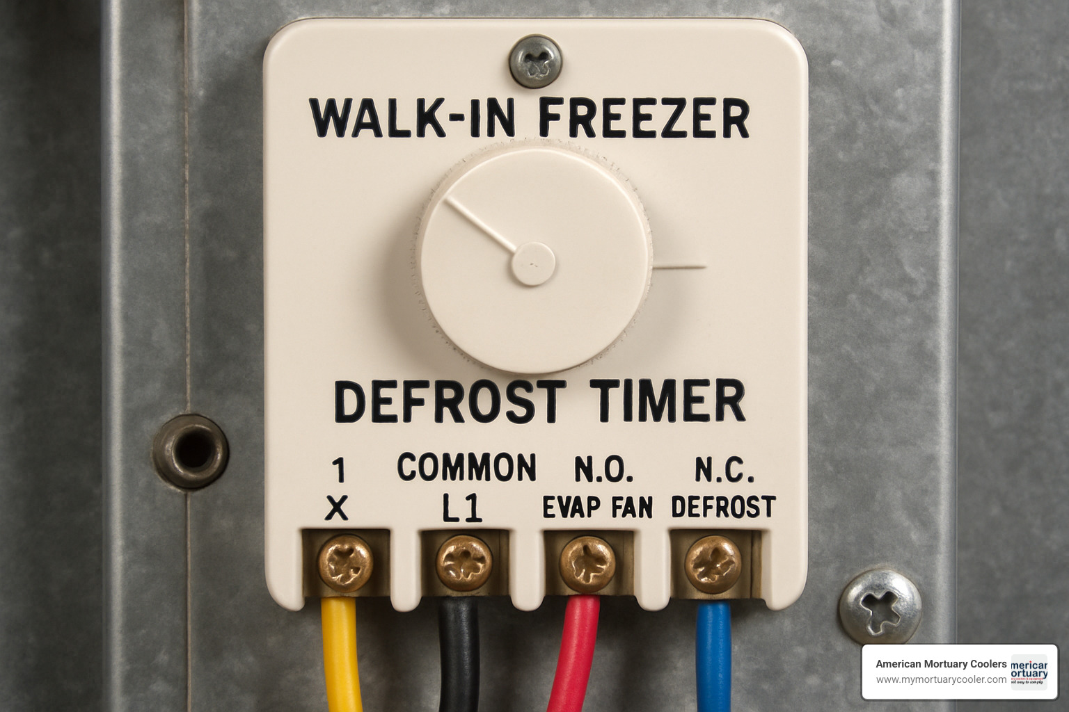
How the Defrost Timer Is Wired & Adjusted
Defrost timers use both normally open (N.O.) and normally closed (N.C.) contacts to control different circuits. During normal operation, N.C. contacts power the evaporator fans and compressor circuit, while N.O. contacts remain open.
When defrost initiates, the timer reverses: N.C. contacts open (stopping fans and compressor), while N.O. contacts close (energizing defrost heaters).
Cycle frequency adjustment is critical. Too frequent defrost cycles waste energy and can cause temperature fluctuations. Too infrequent cycles allow excessive frost buildup.
Terminal identification varies by manufacturer, but common designations include: - T: Timer motor (continuous power) - 1: Compressor/fan circuit (N.C.) - 2: Defrost heater circuit (N.O.) - 3: Common terminal
Controlling the Liquid-Line Solenoid Valve
The liquid-line solenoid valve controls refrigerant flow to the evaporator and is essential for proper pump-down operation. Most solenoids operate on 24V AC.
The thermostat provides the signal to open the solenoid when cooling is needed. When the space temperature rises above the thermostat setting, it energizes the solenoid coil, allowing refrigerant flow.
Pump-down operation occurs when the thermostat is satisfied. The solenoid closes, stopping refrigerant flow, but the compressor continues running until suction pressure drops to the low-pressure switch setting.
Integrating Safety Devices in Heater Circuits
High-limit fuse links protect defrost heaters from overheating. These single-use devices open permanently if heater temperature exceeds safe limits, typically around 200°F.
Thermal overloads provide resettable protection for fan motors and other components. Unlike fuse links, thermal overloads automatically reset when temperature drops to safe levels.
Crankcase heater logic ensures the heater operates only when the compressor is off, preventing overheating the oil when the compressor is running.
Installation Best Practices & Common Pitfalls
Getting your commercial walk in freezer wiring diagram installed correctly isn't just about following the schematic - it's about understanding the real-world challenges that can make or break your system.
The biggest difference between a smooth installation and a costly callback often comes down to moisture control. Walk-in freezers create extreme temperature differentials that can wreak havoc on electrical systems if you don't take the right precautions.
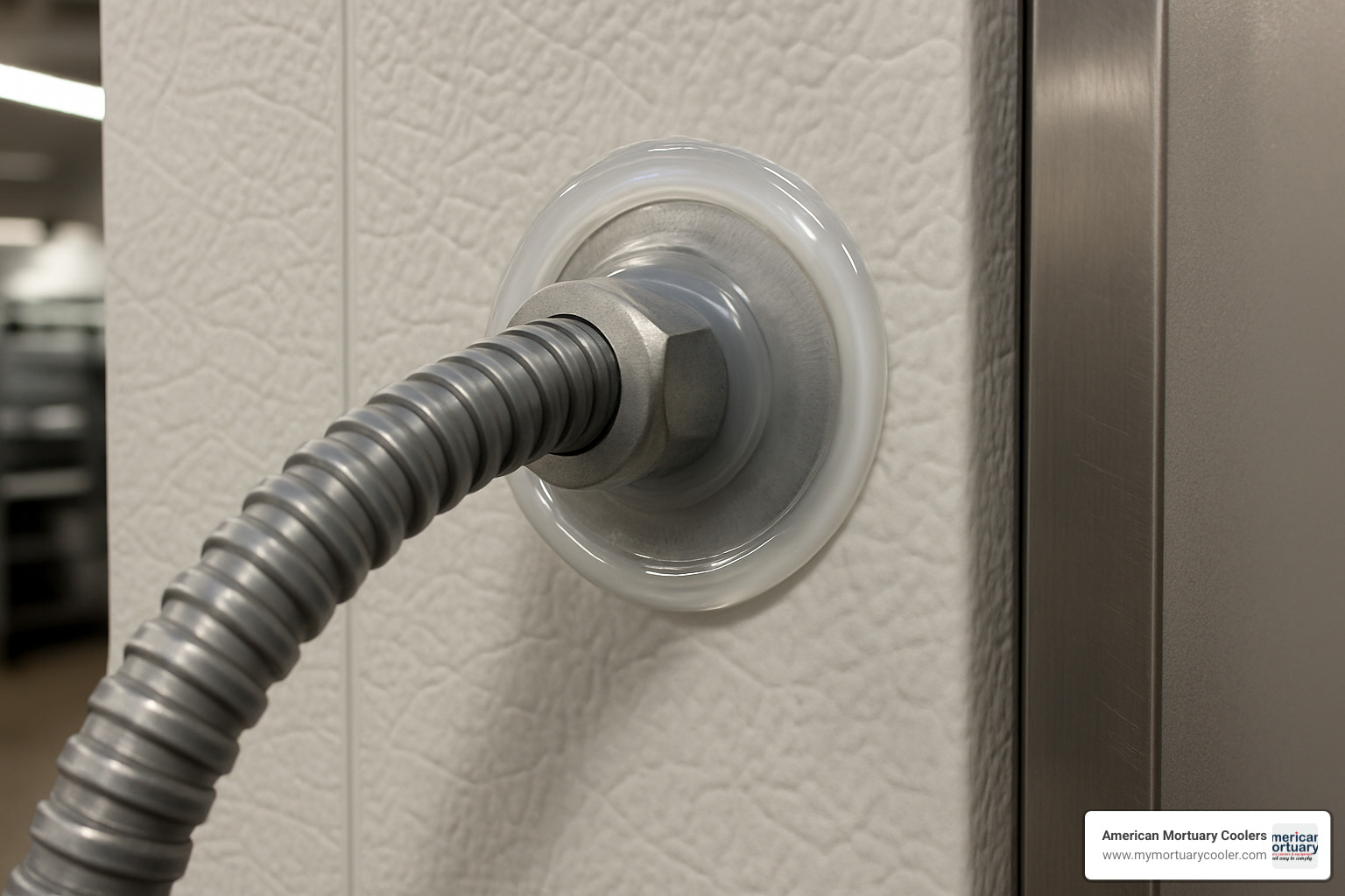
Liquidtight conduit is your best friend for all entries into the freezer box. Standard EMT or rigid conduit might look fine during installation, but moisture will find its way in through the fittings.
Once you're inside the freezer box, MC cable transitions work well for internal wiring runs. Just make sure to secure everything properly - the constant temperature cycling creates vibration that can loosen poorly secured cables.
Sealing with silicone around every penetration is absolutely critical. Use a high-quality silicone that's rated for low temperatures, and apply it generously around all conduit entries.
Heat tape on drains prevents one of the most common service calls - frozen drain lines. Use self-regulating heat tape that automatically adjusts its output based on temperature.
One mistake that drives us crazy is avoiding timer in condenser placement. We see installers mount the defrost timer in the condensing unit because it seems convenient, but this creates problems with the pump-down sequence.
Field Mistakes That Kill Compressors
Flooded starts are the number one killer of walk-in freezer compressors. Liquid refrigerant accumulates in the compressor crankcase during off cycles. When the compressor starts up, that liquid flashes to vapor instantly, washing oil away from bearing surfaces.
The solution is proper pump-down operation. Your liquid-line solenoid must close before the compressor shuts off, and the low-pressure switch needs to be set correctly.
Non-interlocked heaters create their own problems. If your defrost heaters can run while the compressor is operating, they're fighting each other - one trying to add heat while the other removes it.
Improper grounding might not kill your compressor, but it can kill someone. All metal components need to be bonded to the equipment grounding conductor, and GFCI protection is required for all 115V circuits.
Documentation You Must Keep On-Site
Manufacturer schematics should be your first priority. Keep the original wiring diagram in a protective sleeve mounted right inside the electrical panel.
As-built drawings are just as important if you made any field modifications during installation. Future service technicians need to know what was actually installed.
Maintenance logs help you track system performance over time. Record defrost cycle frequency, operating pressures, and any service work performed.
At American Mortuary Coolers, we've learned that the difference between a reliable installation and a problematic one often comes down to these details.
Troubleshooting Checklist & Quick Tests
When your walk-in freezer decides to take an unscheduled vacation from keeping things cold, don't panic. A systematic approach to troubleshooting will save you time, money, and the headache of replacing parts that aren't actually broken.
Start with the basics. Is power actually reaching the system? Check that all disconnects are closed and control fuses are intact.
No-cool diagnostics follow a logical path through your commercial walk in freezer wiring diagram. First, verify the thermostat is calling for cooling. Next, confirm the liquid-line solenoid is energized. Then check that you have adequate suction pressure to satisfy the low-pressure switch. Finally, verify the compressor contactor is pulling in.
Blown control fuses are like canaries in a coal mine - they're telling you something's wrong in the control circuit. Common culprits include failed contactor coils, grounded control wiring, or moisture sneaking into electrical components. You can find discussions about walk-in freezer control fuse issues in technical forums.
Fan problems often trace back to defrost operation issues. If your evaporator fans refuse to restart after a defrost cycle, check the defrost timer position and any fan delay settings.
Heater troubles can be sneaky to diagnose. A heater stuck in the "on" position will cause high temperatures and waste serious energy. Use an amp clamp to verify heater operation - they should only draw current during defrost cycles.
Solenoid humming usually means mechanical trouble preventing the valve from opening fully. This could be debris in the valve seat, low voltage to the coil, or mechanical damage.
Continuity tests and amp-clamp readings are your best friends for pinpointing electrical faults. A simple multimeter can verify if circuits are complete, while amp readings tell you if components are actually working under load.
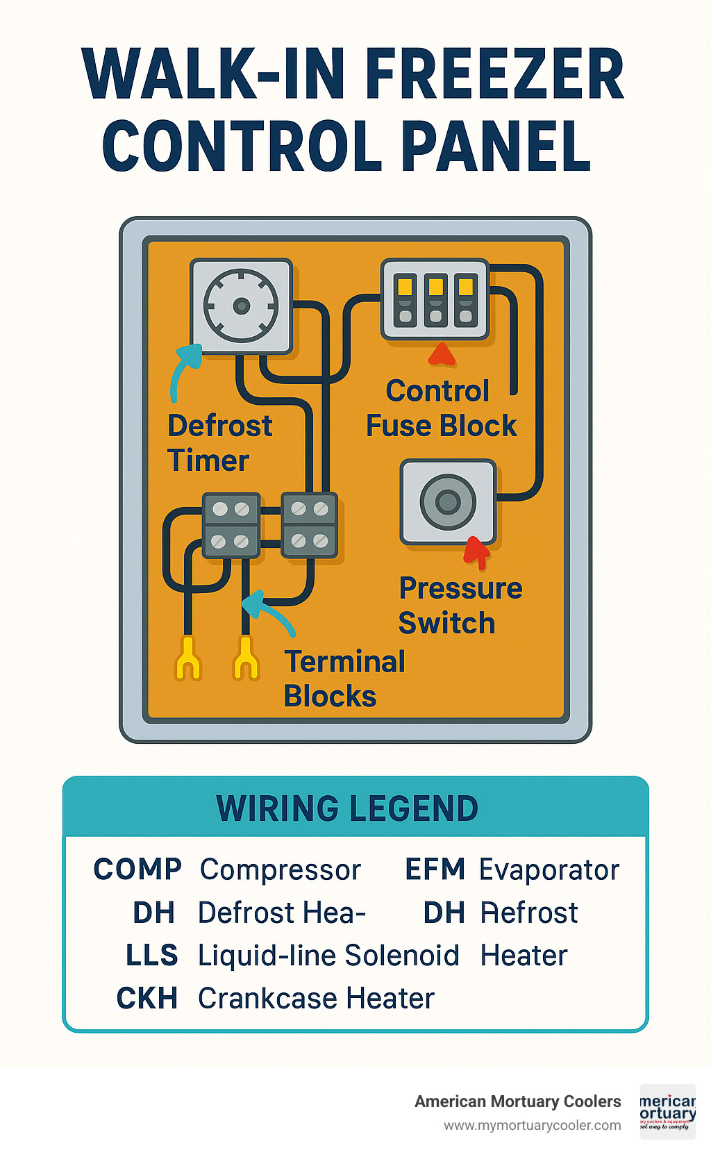
Commercial Walk-In Freezer Wiring Diagram Reference Points
Every commercial walk in freezer wiring diagram has key reference points that make troubleshooting much easier when you know where to look.
Control fuse blocks live in the condensing unit control panel and protect low-voltage control circuits from overcurrent damage. Standard ratings are typically 3A or 5A.
Timer terminals vary by manufacturer but follow common conventions. The timer motor terminal gets continuous power to advance the cam mechanism. Switching terminals control different circuits based on where the cam sits in its rotation.
Pressure switches have adjustable cut-in and cut-out settings. For R-404A systems, high-pressure switches typically cut out around 450 PSI. Low-pressure switches cut out around 2 PSI and cut in around 20 PSI.
Component labels should clearly identify each device's function using standard abbreviations. Look for COMP (compressor), EFM (evaporator fan motor), DH (defrost heater), LLS (liquid-line solenoid), and CKH (crankcase heater).
When to Call in a Refrigeration Specialist
Sometimes the smart move is knowing when you're in over your head. Complex faults involving refrigeration system problems require specialized knowledge and tools that most general electricians don't have.
Warranty concerns should always involve the manufacturer or their authorized service representatives. Attempting repairs on warranty equipment can void your coverage and create serious liability issues.
Code violations found during troubleshooting must be corrected by qualified personnel before the system goes back into service. Don't compromise safety just to get a system running quickly.
Frequently Asked Questions about Walk-In Freezer Wiring
Let's tackle the most common questions we hear from technicians working with commercial walk in freezer wiring diagrams.
Why do my evaporator fans stop during defrost?
This catches many technicians off guard, especially those used to working on coolers. In freezer applications, evaporator fans must stop during defrost cycles - and there's a good reason for this.
When defrost heaters kick on, they're pumping heated air into the evaporator coil area to melt frost buildup. If the fans kept running, they'd blow that hot air throughout your freezer space, causing temperature spikes.
The defrost timer includes special contacts that cut power to the fans when defrost starts. This is completely different from cooler applications, where fans typically keep running during simple off-cycle defrost.
Can I power both compressor and heaters from one circuit?
Since the compressor and defrost heaters never operate simultaneously in a correctly wired system, you can technically power both from a single 20A circuit.
However, you'll need local disconnects for each component to meet code requirements. The defrost timer must provide proper interlocking to ensure these loads never conflict.
Many installers prefer separate circuits for easier troubleshooting. When you're standing in front of a malfunctioning unit at 2 AM, having dedicated circuits makes diagnosis much simpler.
What wire gauge should I use for a 20A 208V three-phase feed?
For a 20A, 208V three-phase condensing unit, 12 AWG copper conductors with 75°C insulation rating will handle the load with proper margin.
The key consideration is voltage drop over distance. You need to keep voltage drop below 3% of supply voltage - that's 6.24V for a 208V system. For longer runs, you might need to step up to 10 AWG conductors.
Don't forget about the evaporator circuit - it typically needs 12 AWG as well for the defrost heaters, even though they only draw about 7.8A.
At American Mortuary Coolers, we've seen installations where undersized conductors caused voltage drop issues, leading to weak compressor starting and shortened equipment life.
Conclusion
Getting your commercial walk in freezer wiring diagram right the first time saves you headaches, callbacks, and potentially expensive equipment damage down the road. Walk-in freezers aren't just bigger versions of household freezers - they're complex systems with multiple interlocked circuits that need to work together seamlessly.
Remember the fundamentals that separate successful installations from problem jobs: always start with the manufacturer's specific wiring diagram for your unit. Install those disconnects where you can actually see the equipment they're protecting. Make sure your defrost timer controls both the fans and heaters properly - this is where most rookie mistakes happen.
Don't forget the details that matter long-term. Seal every penetration like your reputation depends on it, because moisture infiltration will come back to haunt you. Document any changes you make from the original design.
At American Mortuary Coolers, we've been delivering rugged, custom cold storage solutions across the contiguous 48 states for years. From our Tennessee headquarters to installations everywhere from small-town funeral homes to large metropolitan facilities, we've seen what works and what doesn't. Proper wiring isn't just about following code - it's about creating systems that funeral directors can count on when they need them most.
When you're standing in front of a control panel at 2 AM trying to figure out why the system isn't working, you'll appreciate having done things right the first time. The complexity of modern walk-in freezer controls means there's no room for shortcuts or guesswork.
Here's the bottom line: when you're not sure about something, don't wing it. Consult the manufacturer's documentation, ask questions, and don't hesitate to bring in a qualified refrigeration specialist for the tricky stuff.
For more technical guidance and information about our walk-in freezer options, visit our resource center. We're here to help funeral industry professionals succeed with reliable, properly installed cold storage solutions.